Motivation: weak forces on DualPanto might be a result of a depleted battery. But how to find out?
Analog Electronics
- digital output on Arduino: things happen one layer further down
- analog electronics like resistors
- power plays a role (LED might burn out, battery depletes, etc.)
Ohm’s law
(Spannung Widerstand Stromstärke)
- respectively
- or

Electrical power
(Leistung Spannung Stromstärke)
- which gives
Example I
- Red LED specs: 1.8 - 2.2V, 20mA
- (using Ohm’s law)
- Battery specs: 2V
- result: voltage (Spannung) is chosen correctly, so LED will allow 20mA of current (Stromstärke) flow
- 2V 20mA 40mW of power in light (Leistung)
Example II
- 5V USB instead of battery
- 2.5 times the voltage 6.25 times the power (250mW)
- more energy accumulates than the LED can dispense gets hot boom
Example III
- still 5V USB
- LED specs now: 3.8V, 20mA
- 1.3 times the voltage 1.7 times the power (not a big factor)
- surprisingly, the LED blows too, because it does not follow Ohm’s law…
Non-ohmic Devices / Behavior
Non-ohmic devices are pretty common and quite useful
Light bulb
- resistance of filament increases with its temperature (ingenious control loop)
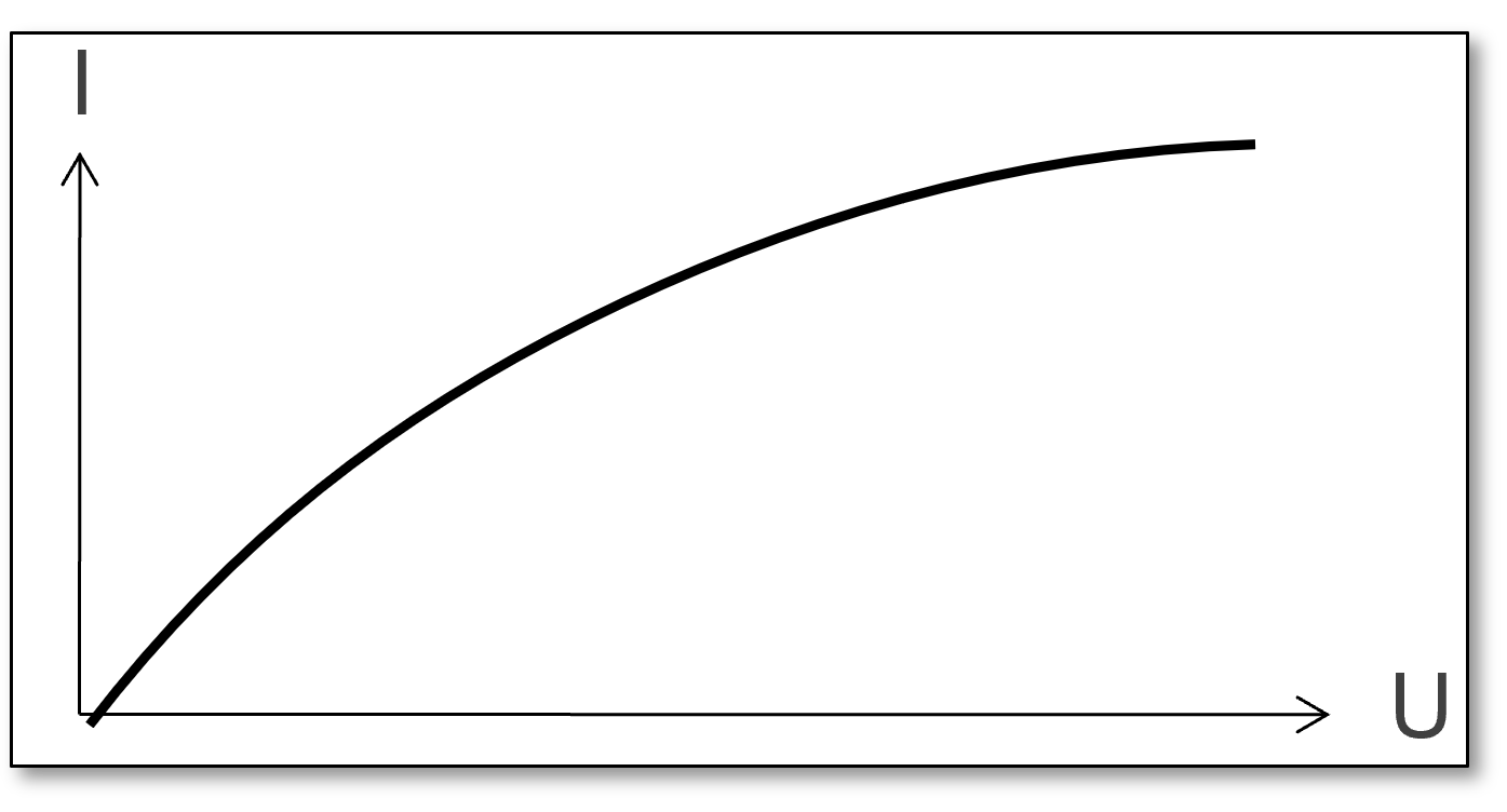
LED
- resistance decreases with its voltage (steep slope)
- large variations in current possible
- works in small voltage interval

Resistors
- implement electrical resistance as a circuit element
- idea: fixing non-ohmic devices by adding an ohmic device in series
- resistor has high resistance almost constant we can increase the voltage and things will be fine
- variable resistor (i.e. using rotatable knob): can be used to adjust circuit elements (such as a volume control or a lamp dimmer), or as sensing devices for heat, light, humidity, force, or chemical activity.
- what resistance for LED?
- subtract voltage drop over LED: , e.g.
- apply Ohm’s law: , e.g.
- what resistance for multiple LEDs?
- principally same as above
- LEDs in series: voltage drop adds up (limits possible amount of LEDs per branch)
- LEDs in parallel: same voltage as for single LED on each branch (overall resistance drops battery delivers more current, strong enough source needed)
- single resistor for same LED in parallel? Needs lower resistance for higher current has to be bigger to dissipate more heat
- two identical resistors in parallel:
- two resistors in parallel (general):
- resistors in parallel (general):

Zener diode
- is a special type of diode designed to reliably allow current to flow “backwards” when a certain set reverse voltage, known as the Zener voltage, is reached
- a modified diode (lets current through in just one direction), that lets current pass in the second direction as well, as soon as some specific voltage is reached
- or scientifically speaking: an abrupt, heavily doped p–n junction, in which case the reverse conduction occurs due to electron quantum tunnelling in the short distance between p and n regions
Battery tester
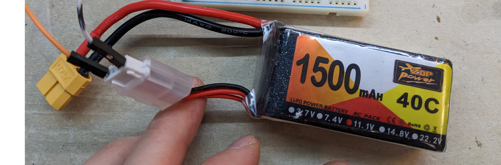
our batteries:
- 3 3.7V 11.1V (3S meaning three cells in series)
- 1500mAh: 1.5A 11.1V 16.65W for 1 hour
- 40C: max discharge rate (current): 40 1500mA 60A (with 11.1V this discharges battery in 1.5 minutes) would explode in case of short circuit
- cut off voltage (red LED): 9.0V; nominal voltage (yellow LED): 11.1V; maximum voltage (green LED): 12.6V
- fitting Zener diode: subtract 2V drop over the LED
- fitting resistor: gets lower from red to yellow to green because of parallelity
Breadboard
issues:
- unreliable: cables fall out of the board
- unsafe: potential short circuit
- (large, impractical)
Electronic devices (historically)
- case (structural)
- electronic components
- wiring (flexible)
Printed circuit board (PCB)
a board base for physically supporting and wiring the components in electronics
- combining structure + wiring
- components are soldered
- fiberglass board covered with copper layer
- etch away areas to create conductive traces
side effects:
- mass production (PCB vs. breadboard = injection molding vs. 3D printing)
- reliability
- miniaturization
KiCad Process
essentially a large drawing program
- Circuit design: paper / breadbord
- Draw schematic: recreate circuit design in KiCad (symbolic / logical, not physical)
- Assign footprints: use BIS library (true size etching plan, model of physical PCB)
- Board layout: creative arrangement of components, routes, text, etc. (finished model of physical PCB)
- Fabrication
- Assembly (soldering)
Prototyping PCBs
- use fiber laser for engraving
Manufacturing PCBs in Shenzen
- using photoengraving
- photosensitive film selectively hardens
- then use chemicals to etch away the unprotected copper
- for more complex circuits (routes crossing), even multilayer PCBs are possible
Solder mask
- a thin layer of polymer to prevent oxidation and solder bridges between closely spaced solder pads on a PCB
Take home message
You can make your own electronics and PCBs for your own software / hardware start-up